Plenty of shops buy advanced equipment and still struggle with inconsistent results. The problem is rarely the label on the machine. It usually reflects a weak understanding of how the machine moves, how the tool is presented to the part, and how those motions affect accuracy under load.
That is why machine kinematics matter so much in five-axis work. For manufacturers, plant leaders, and procurement teams evaluating machining capability, precision is not just a spindle-speed conversation. It is a motion-control conversation. Tool angle, axis arrangement, pivot distance, rotary behavior, and interpolation quality all influence whether a machine cuts smoothly or introduces error. When five-axis machining performs well, kinematics are working in the background with discipline. When performance slips, they are often the first place worth examining.
Motion Geometry Changes Cutting Reality
Axis Layout Defines Machine Behavior
Five-axis machining expands what a machine can do by allowing the cutter and the workpiece to move through more complex orientations. That flexibility makes difficult geometries easier to reach, but it also raises the stakes. In three-axis work, tool position is the dominant concern. In five-axis work, position and orientation are inseparable. A tool can reach the correct point in space and still create poor results if its angle is slightly off, its pivot path is inefficient, or a rotary motion introduces instability. Kinematics determines how those motions are calculated and executed, which means it directly shapes surface quality, tolerance control, and tool behavior.
The physical arrangement of rotary and linear axes has a major effect on how a machine behaves during a cut. Some configurations tilt the spindle, others rotate the table, and many combine both movements in different ways. That architecture changes how mass moves, how quickly the machine can reorient, and how errors accumulate across a toolpath. Buyers comparing 5-axis machines often focus on size, speed, and control features, but the real difference in precision often comes from the kinematic structure underlying those specifications. A machine with a favorable axis layout for the intended part family can maintain cleaner motion and more stable tool presentation over long, demanding cycles.
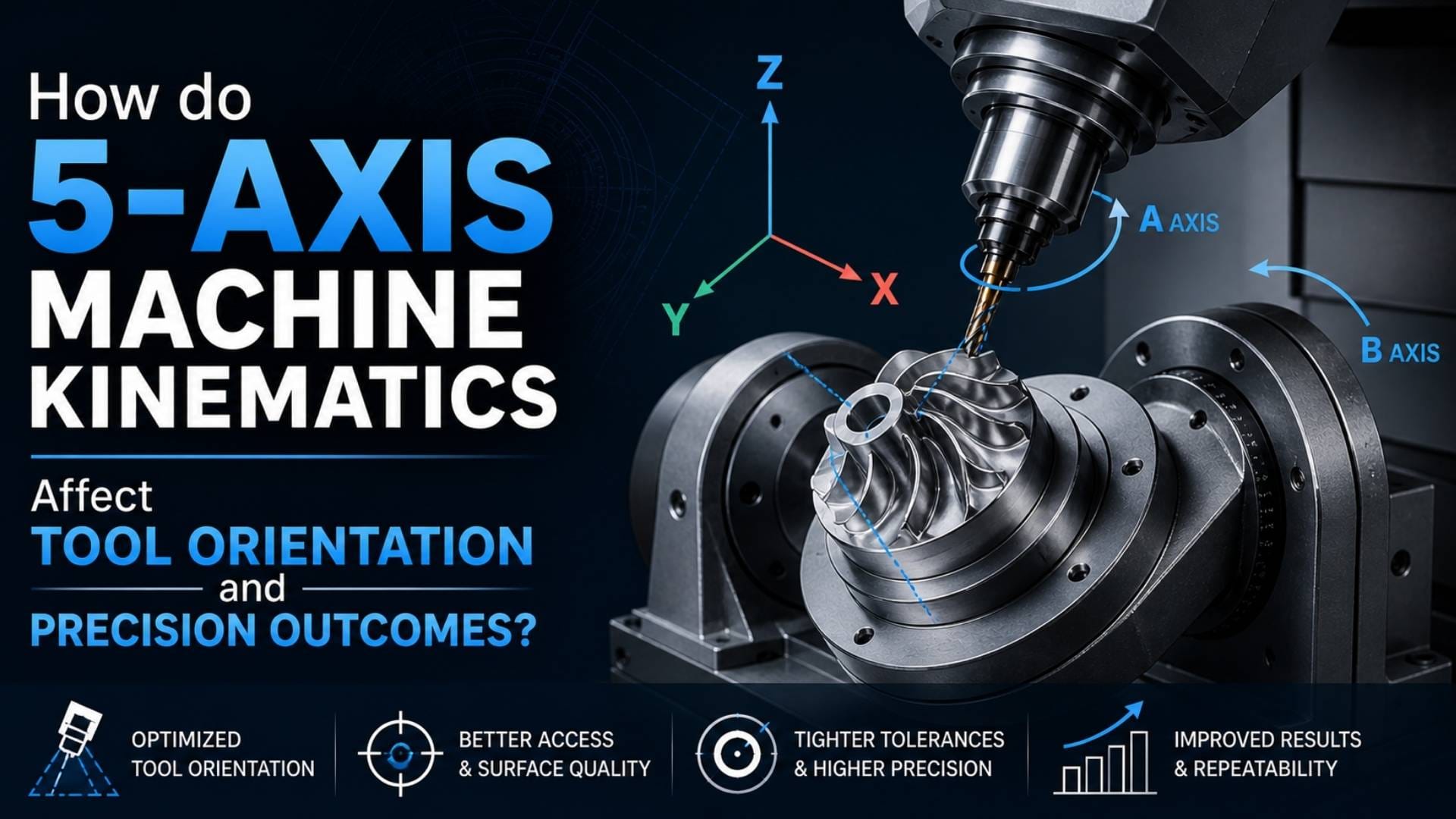
Tool Angle Controls Surface Contact
Tool orientation is not a visual detail. It changes the actual mechanics of cutting. As the tool tilts, the contact point between the cutting edge and the material shifts. That affects chip formation, cutting pressure, heat concentration, and the way forces travel through the spindle and machine frame. If the kinematics support smooth, predictable orientation changes, the machine can maintain a stable cutting condition over complex contours. If they do not, the tool may chatter, rub, or leave inconsistent marks on the part. Precision outcomes are often shaped by these small orientation decisions long before a part ever reaches final inspection.
Pivot Distance Alters Error Magnification
One of the most important and least understood factors in five-axis machining is pivot distance. The farther the tool tip sits from the center of rotary motion, the more a small angular error can become a measurable positional error at the cutting edge. This matters because five-axis work relies on constant angular adjustments. Even a modest deviation in a rotary axis can create noticeable error when a long tool assembly is involved. Kinematics influence how those angles are calculated and how reliably the control compensates for them. Shops chasing precision on deep cavities or complex surfaces ignore pivot effects at their own risk, because the machine may be accurate in theory while drifting at the tool tip.
Also Read:
- Water Jet Machining – Working Principle, Advantages and Disadvantages with Application
- CNC Machining: Definition, Working Principle, Types, Advantages and Applications
- Difference Between NC and CNC Machine
Rotary Motion Shapes Dynamic Stability
Rotary axes do not just position the part or spindle. They change the machine’s dynamic character throughout the cut. When a table rotates, the workpiece’s center of gravity shifts. When a spindle head tilts, the load path through the machine structure changes. These moving conditions affect stiffness, acceleration response, and vibration behavior. Good kinematics allow those transitions to happen with minimal disruption, preserving smooth tool engagement as the part geometry evolves. Poorly matched kinematics can create a machine that looks capable on paper but behaves inconsistently when real material removal begins. That gap between theoretical travel and usable precision is where many production frustrations start.
Smooth Interpolation Preserves True Geometry
Five-axis accuracy depends on more than the destination point. It depends on the path taken to get there. Interpolation quality determines whether multiple axes move together in a coordinated way or create tiny hesitations and corrections that degrade the cut. On sculpted surfaces or aerospace-style contours, those small motion defects can produce visible witness lines, uneven cusp patterns, and geometry drift. Kinematics sits at the heart of that coordination because it defines how control commands translate into actual machine motion. A machine that handles interpolation cleanly can maintain the intended tool vector through changing curvature. A weaker system may technically complete the toolpath while quietly sacrificing finish and dimensional consistency.
Collision Avoidance Can Distort Orientation
One promise of five-axis machining is improved access to hard-to-reach features, but that access often depends on aggressive tool tilting to avoid holders, fixtures, and machine structures. Every time a programmer alters orientation to avoid interference, the cutting condition changes. Kinematics determines how much freedom the machine has to make those adjustments without compromising precision. If the motion envelope is tight or the rotary axes approach their limits, the machine may force less favorable tool angles, increasing deflection or reducing finish quality. In practice, collision avoidance is not only a safety function. It is a precision issue because it shapes the orientations the machine can use while still producing the required geometry.
Axis Limits Influence Process Strategy
Every five-axis machine has axis travel limits, speed limits, and zones where motion becomes less efficient. Kinematics defines how those constraints appear in actual production. A machine may be capable of achieving a target tool angle, but only by moving near a rotary limit where acceleration slows, or reversal becomes awkward. That can affect cycle time, surface finish, and repeatability. For shops machining families of similar parts, understanding these kinematic boundaries is critical. The goal is not just to prove that a part can be machined. The goal is to ensure that it can be machined repeatedly, with stable orientation control and without forcing the machine into less reliable motion patterns.
Better Motion Produces Better Parts
Five-axis machining earns its value through control of orientation, not just access. That is the point many purchasing discussions miss. Kinematics decide how the machine tilts, rotates, compensates, and interpolates under real cutting conditions, and those factors shape everything from surface finish to tolerance stability and tool life.
For manufacturers, operations leaders, and owners assessing machining capability, the practical lesson is clear. Precision does not come from axis count alone. It comes from how intelligently those axes are arranged, calibrated, and used. When the kinematic model fits the work, the tool maintains the right attitude, the process remains stable, and the machine delivers the kind of repeatable accuracy that high-value parts demand.