
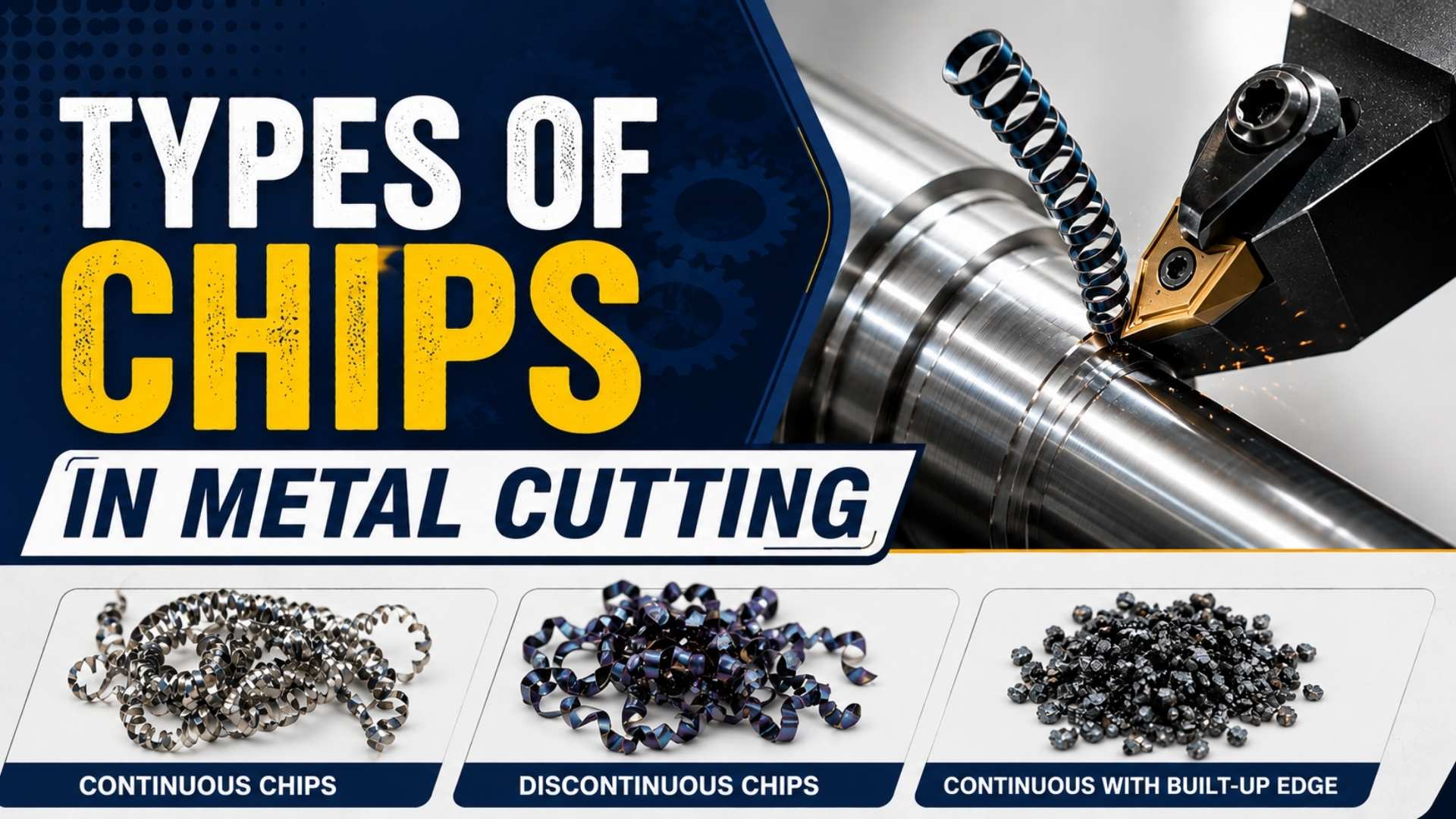
During any metal machining operation – turning, milling, or drilling – the cutting tool removes material and produces metal chips. The type of chip formed has a direct impact on surface finish quality, tool life, power consumption, and overall machining efficiency.
There are three main types of chips in metal cutting:
- Continuous Chips
- Discontinuous Chips
- Continuous Chips with Built-Up Edge (BUE)
Understanding what causes each type – and when each appears – helps machinists optimize cutting parameters and avoid defects.
1. Continuous Chips

What Are Continuous Chips?
Continuous chips are long, unbroken ribbon-like chips formed when a ductile material is machined under favorable cutting conditions. There is no fracture or segmentation in the chip – it flows smoothly over the tool face.
Conditions That Produce Continuous Chips
- Ductile workpiece material (e.g., mild steel, aluminum)
- High cutting speed
- Large rake angle on the cutting tool
- Minimum friction at the chip-tool interface
- Small depth of cut
- Use of cutting fluid/coolant
Advantages of Continuous Chips
- Superior surface finish – smooth, uninterrupted chip flow means less surface damage
- Lower heat generation – reduced friction keeps temperatures down
- Lower power consumption – cutting forces remain stable
- Longer tool life – minimal wear due to low friction
Disadvantages
- Long continuous chips can tangle around the tool or workpiece, creating a safety hazard
- Chip disposal becomes difficult on CNC machines without chip breakers
2. Discontinuous Chips

What Are Discontinuous Chips?
Discontinuous chips (also called segmented chips) are short, broken chip segments produced during machining. Instead of a smooth flow, the chip fractures repeatedly as material is removed.
Conditions That Produce Discontinuous Chips
- Brittle workpiece materials (e.g., cast iron, brass, bronze)
- Low or high cutting speed
- Small rake angle
- High friction at the chip-tool interface
- Large depth of cut
- Low feed rate
Advantages of Discontinuous Chips
- Easy chip disposal – short segments are simple to collect and remove
- Better surface finish on brittle materials – fracture happens cleanly
- Reduced power consumption during brittle material machining
- Good tool life when machining appropriate (brittle) materials
Disadvantages
- When discontinuous chips form in ductile materials, they indicate poor cutting conditions, resulting in rough surface finish and accelerated tool wear
- Interrupted cutting can cause vibration and chatter
3. Continuous Chips with Built-Up Edge (BUE)

What Are BUE Chips?
BUE chips are a variation of continuous chips where a hardened layer of workpiece material becomes welded to the cutting tool’s nose. This hardened layer is called the Built-Up Edge. Chips then flow over and break against this edge rather than the original tool face.
How Does a Built-Up Edge Form?
When machining ductile materials at low-to-medium cutting speeds with high friction at the tool-chip interface, extreme heat and pressure build up at the tool nose. The adjacent workpiece material softens, gets compressed, and metallurgically bonds (welds) to the tool. This welded mass is the built-up edge.
As machining continues, pieces of the BUE periodically break off. Some are carried away in the chip, and some remain on the machined surface, causing roughness.
Conditions That Promote BUE Formation
- Ductile workpiece material
- Low cutting speed (insufficient to clear heat)
- Small rake angle
- High feed rate
- Lack of cutting fluid (high friction, high temperature)
- Absence of anti-friction coatings on tool
Advantages of BUE
- The hardened BUE temporarily protects the tool face from direct contact with the workpiece
- Can slightly extend tool life in the short term (before BUE breaks off)
Disadvantages of BUE
- Poor surface finish – broken BUE fragments embed in or scratch the workpiece surface
- Changes the effective rake angle of the tool, altering cutting forces unpredictably
- Dimensional inaccuracy – the effective tool geometry shifts as BUE builds and breaks
- Promotes accelerated tool wear over time when BUE repeatedly breaks off
How to Prevent BUE Formation
- Increase cutting speed (high speed clears the heat zone)
- Use a larger rake angle tool
- Apply cutting fluid generously
- Use coated tools (TiN, TiAlN coatings reduce friction)
- Reduce feed rate
Comparison Table: Continuous vs. Discontinuous vs. BUE Chips
| Factor | Continuous | Discontinuous | BUE Chips |
| Material type | Ductile | Brittle / Hard ductile | Ductile |
| Rake angle | Large | Small | Small |
| Cutting speed | High | Medium or High | Low or Medium |
| Friction (chip-tool) | Minimum | Maximum | Maximum |
| Depth of cut | Small | High | Medium |
| Surface finish | Excellent | Good (brittle) / Poor (ductile) | Poor |
| Tool life | Long | Good (brittle materials) | Reduced (long-term) |
| Chip disposal | Difficult | Easy | Moderate |
Factors Affecting the Type of Chip Formed
Several variables determine which chip type forms during machining:
- Workpiece material – ductile vs. brittle is the most influential factor
- Cutting speed – higher speeds favor continuous chips; low speeds promote BUE
- Rake angle – larger angles produce continuous chips
- Feed rate – excessive feed promotes BUE or discontinuous chips
- Depth of cut – deeper cuts often produce discontinuous chips
- Cutting fluid – proper lubrication prevents BUE and reduces heat
- Tool material and coating – coated tools resist BUE formation
FAQs: Frequently Asked Questions
Continuous chips provide the best surface finish, especially when machining ductile materials like mild steel at high cutting speeds with adequate lubrication.
Brittle materials like cast iron fracture naturally during machining. The segmented chip is a result of the material’s inability to deform plastically, which actually leads to a cleaner cut surface in these materials.
Increase cutting speed, use sharp tools with a positive rake angle, apply cutting fluid, and consider using coated tools (TiN or TiAlN coatings significantly reduce BUE tendency).
Yes. Long continuous chips can tangle around the spindle, tool, or workpiece and pose a serious injury risk. CNC machines use chip breakers in the tool insert geometry to prevent this.
Cast iron is a brittle material, so it always produces discontinuous (segmented) chips, regardless of cutting speed.
Summary
The three types of chips in metal cutting – continuous, discontinuous, and BUE – each indicate different machining conditions and produce different outcomes for surface quality, tool life, and efficiency. Selecting the right cutting speed, feed, rake angle, and coolant helps machinists control which chip type forms and optimize the machining process accordingly.
Nice Article
Nice notes bro
Welding ke bhi note deejiye
Full notes welding
Thank you Sir. The Information is Very Useful.