What is Fused Deposition Modeling (FDM)?
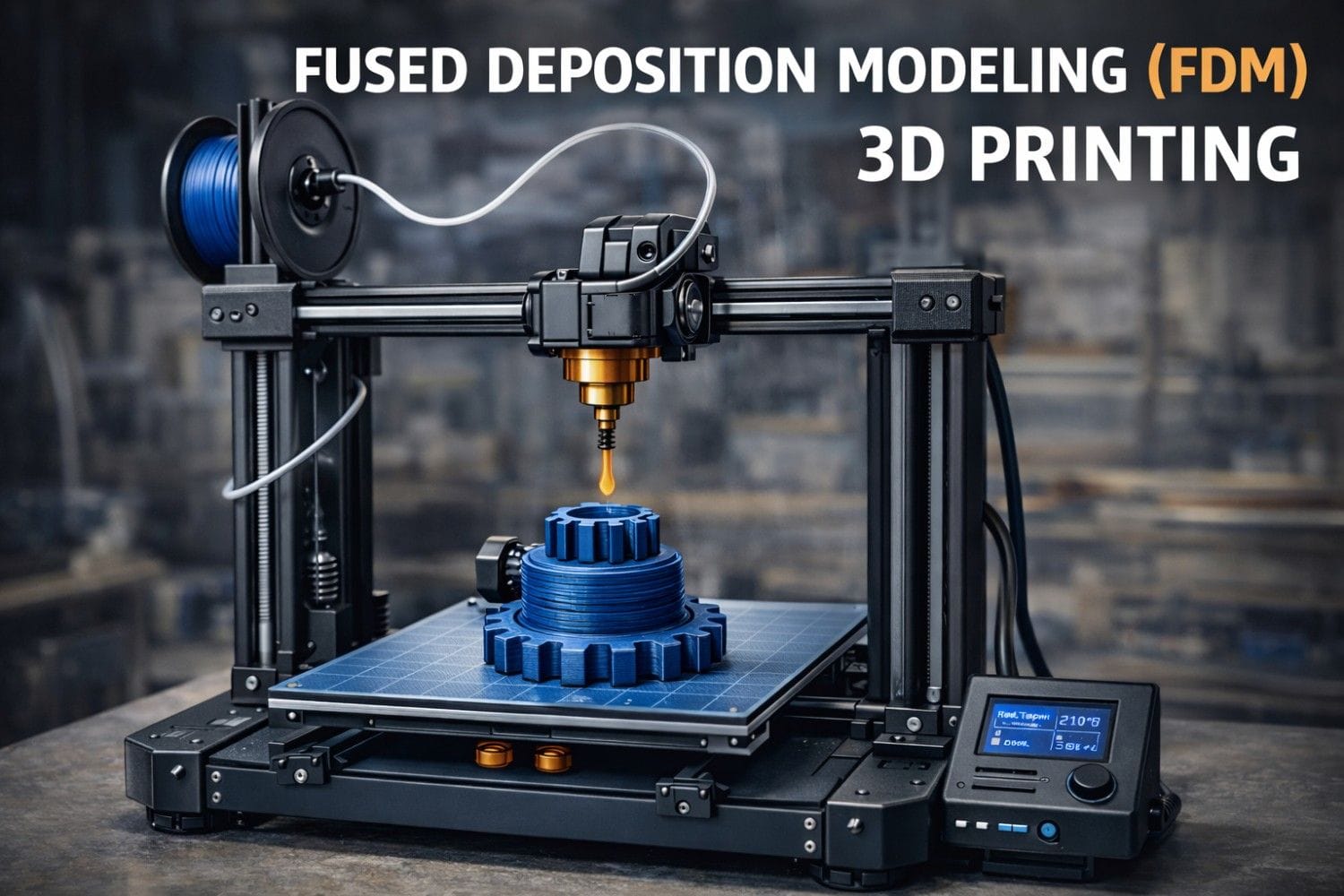
Fused Deposition Modeling (FDM) is an additive manufacturing process in which thermoplastic material is heated, melted, and extruded through a nozzle to build a part layer by layer from a digital 3D model.
It is one of the most widely used 3D printing technologies in:
- Mechanical engineering prototyping
- Automotive component development
- Manufacturing fixtures and jigs
- Educational and research laboratories
- Consumer product design
FDM is also referred to as Fused Filament Fabrication (FFF) (the open-source term).
Working Principle of FDM 3D Printing
The working of FDM is based on material extrusion and layer-by-layer solidification.
Step-by-Step Working Process
- 3D Model Creation
- CAD model is created using software like SolidWorks, Fusion 360, or CATIA.
- The model is exported in STL or OBJ format.
- Slicing
- Slicing software (e.g., Cura, PrusaSlicer) converts the model into:
- Layers
- Toolpaths
- G-code instructions
- Slicing software (e.g., Cura, PrusaSlicer) converts the model into:
- Filament Feeding
- Thermoplastic filament (PLA, ABS, PETG, etc.) is fed from a spool into the extruder.
- Melting & Extrusion
- The hot end heats the filament (typically 180°C–260°C).
- Molten material is extruded through a small nozzle (0.2–0.8 mm diameter).
- Layer Deposition
- The nozzle moves in X-Y direction.
- The build platform moves in Z-direction.
- Material solidifies immediately after extrusion.
- Layer Bonding
- Each new layer fuses thermally with the previous layer.
Main Components of an FDM Printer
1. Extruder
- Feeds filament into the hot end.
- Can be direct drive or Bowden type.
2. Hot End
- Heats and melts filament.
- Consists of heater cartridge, thermistor, heat block, and nozzle.
3. Nozzle
- Controls extrusion diameter.
- Common sizes: 0.4 mm (standard).
4. Build Platform (Print Bed)
- Heated bed improves adhesion.
- Typical temperature: 50°C–110°C.
5. Frame & Motion System
- Stepper motors
- Linear rails or rods
- Belts or lead screws
Materials Used in FDM
| Material | Properties | Applications |
| PLA | Easy to print, biodegradable | Prototypes |
| ABS | Tough, heat resistant | Automotive parts |
| PETG | Chemical resistant | Functional parts |
| Nylon | High strength | Gears, bearings |
| TPU | Flexible | Seals, gaskets |
| PC | High temperature resistance | Engineering parts |
Key Process Parameters
For mechanical engineers, understanding parameters is critical.
- Layer height (0.1–0.3 mm)
- Infill percentage (10–100%)
- Printing temperature
- Bed temperature
- Print speed (30–100 mm/s)
- Cooling rate
- Raster angle
- Build orientation
Build orientation significantly affects anisotropic strength.
Advantages of FDM
- Low cost compared to SLA and SLS
- Easy material availability
- Minimal post-processing
- Suitable for rapid prototyping
- Good for functional testing
- Safe for educational use
Disadvantages of FDM
- Visible layer lines
- Lower surface finish
- Anisotropic mechanical properties
- Limited accuracy compared to SLA
- Warping (especially with ABS)
Applications of FDM in Mechanical Engineering
1. Rapid Prototyping
- Concept models
- Design validation
2. Automotive Industry
- Dashboard components
- Custom brackets
- Air ducts
3. Manufacturing
- Jigs & fixtures
- Assembly aids
- Tool holders
4. Aerospace
- Lightweight ducts
- Non-structural interior components
5. Medical
- Prosthetic prototypes
- Surgical guides (non-implant)
FDM vs Other 3D Printing Technologies
| Feature | FDM | SLA | SLS |
| Material | Thermoplastic | Resin | Powder |
| Cost | Low | Medium | High |
| Strength | Moderate | Low | High |
| Surface Finish | Moderate | Excellent | Good |
| Industrial Use | High | Medium | High |
Mechanical Properties Consideration
Because FDM parts are layered:
- Strength is higher in X-Y plane
- Lower strength in Z-direction
- Layer adhesion determines failure mode
- Infill pattern affects stiffness
Design engineers must:
- Optimize build orientation
- Increase wall thickness
- Use proper infill patterns
Common Defects in FDM
- Warping
- Stringing
- Layer shifting
- Under-extrusion
- Delamination
- Poor bed adhesion
Future Trends in FDM
- High-temperature polymers (PEEK, ULTEM)
- Carbon fiber reinforced filaments
- Large-format industrial FDM
- Multi-material printing
- AI-based slicing optimization
Conclusion
Fused Deposition Modeling (FDM) is the most accessible and widely adopted 3D printing technology in mechanical engineering. Its affordability, simplicity, and material versatility make it ideal for prototyping, tooling, and functional part production.
However, engineers must carefully consider:
- Material selection
- Process parameters
- Build orientation
- Mechanical performance
When optimized properly, FDM can produce reliable, cost-effective components for real-world applications.