A spur gear is a cylindrical gear with straight teeth cut parallel to its axis, used to transmit motion and power between parallel shafts. It is the simplest and most widely used gear type, offering high efficiency, easy manufacturing, and accurate speed ratios – making it ideal for clocks, conveyors, automotive transmissions, and industrial machinery.
What Is a Spur Gear?
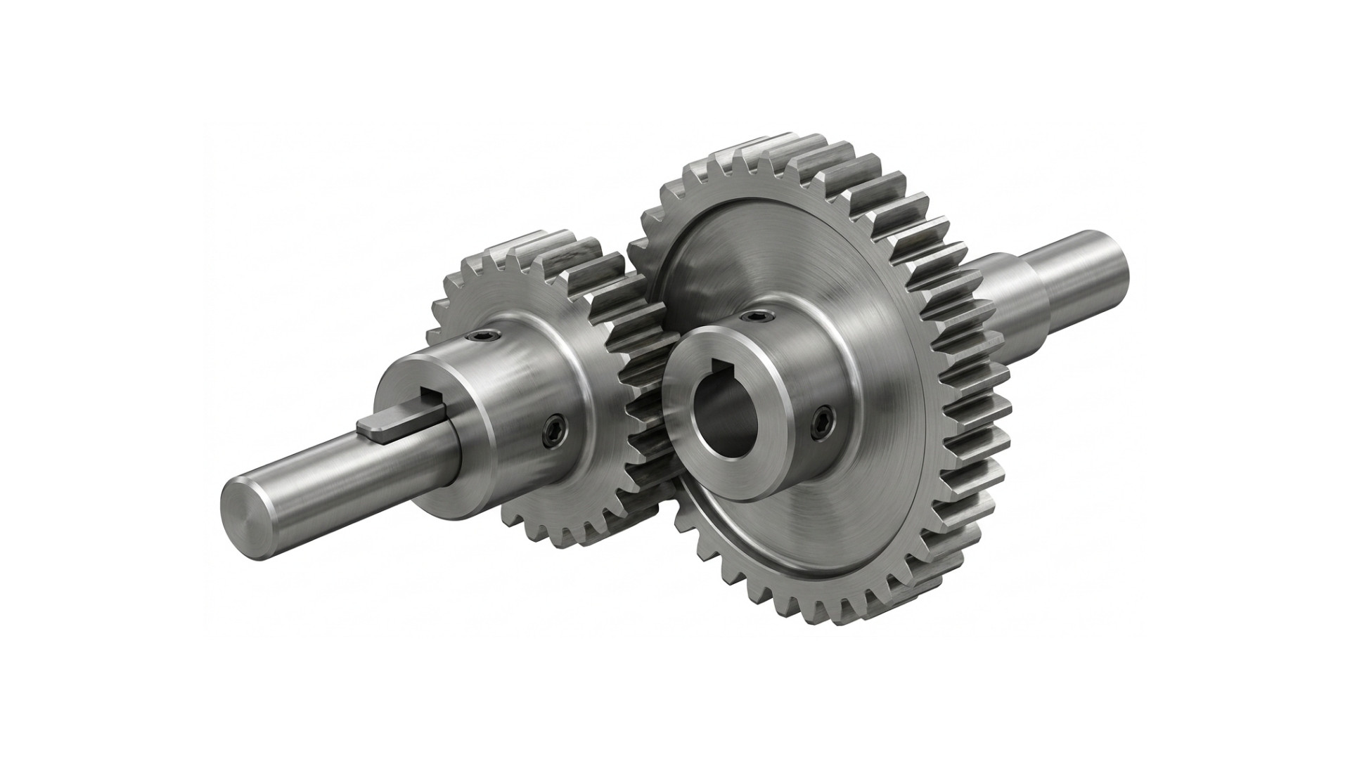
A spur gear is a type of cylindrical gear with straight, flat teeth cut parallel to the gear’s rotational axis. It is designed to mesh with another spur gear – or a rack – mounted on a parallel shaft, transmitting rotational motion and mechanical power efficiently between the two.
The name “spur” comes from the resemblance of the gear’s profile to the spurs worn on riding boots. The teeth radiate outward from the gear’s centre in a straight line, giving the gear its distinctive and easily recognisable appearance.
Key Characteristics
- Straight teeth: Teeth are cut parallel to the gear axis – no helix angle.
- Parallel shafts: Spur gears only transmit power between shafts that are parallel to each other.
- Constant velocity ratio: Because tooth engagement is uniform, the velocity ratio remains constant throughout meshing.
- Simple geometry: Easier to design, manufacture, and inspect than helical or bevel gears.
How Does a Spur Gear Work?
Spur gears work by direct tooth-to-tooth meshing between two or more gears. When a motor or prime mover rotates the driver gear, its teeth interlock with the teeth of the driven gear, transferring rotational motion from one shaft to the other.
Step-by-Step Engagement
- Driver gear rotates: The input shaft turns the driver (smaller) gear in one direction.
- Tooth contact: The teeth of the driver gear push against the teeth of the driven gear at the pitch point.
- Force transmission: The contact force is transferred along the tooth flank, creating a tangential force that rotates the driven gear.
- Direction reversal: External spur gears rotate in opposite directions; internal spur gears rotate in the same direction.
- Speed and torque change: Gear ratio determines whether speed increases (torque decreases) or torque increases (speed decreases).
Simple Example: A clock mechanism uses spur gears to step down the motor’s high speed to the slow, precise rotation of the hour, minute, and second hands. The small pinion gear drives a larger wheel gear – reducing speed while increasing torque.
Gear Ratio formula:
Gear Ratio = Number of Teeth on Driven Gear / Number of Teeth on Driver Gear
Parts of a Spur Gear
Understanding the key parts of a spur gear is essential for selection, design, and maintenance. Below are the most important components.
- Teeth: The protruding elements on the gear’s circumference that mesh with an adjacent gear. Tooth profile is usually an involute curve.
- Pitch Circle: An imaginary circle used as the reference for gear calculations. The pitch circles of two meshing gears are tangent to each other at the pitch point.
- Addendum: The radial distance from the pitch circle to the top (tip) of a tooth.
- Dedendum: The radial distance from the pitch circle to the root (bottom) of a tooth. The dedendum is slightly larger than the addendum to provide clearance.
- Face Width: The length of the gear tooth measured parallel to the gear axis. Wider face = higher load capacity.
- Bore: The central hole through which the gear is mounted on a shaft.
- Hub: The thickened central section surrounding the bore; provides structural support and area for keyway or set screw mounting.
Gear Terminology
A few additional technical terms used when specifying or calculating spur gears:
- Module (m): The ratio of pitch circle diameter to number of teeth (m = d/z). Determines the size of teeth. Larger module = larger, stronger teeth.
- Diametral Pitch (DP): Used primarily in imperial systems; the number of teeth per inch of pitch circle diameter.
- Pressure Angle: The angle between the tooth force and the tangent to the pitch circle. Standard values are 14.5° and 20°.
- Centre Distance: The distance between the axes of two meshing gears; equal to half the sum of their pitch circle diameters.
- Backlash: A small intentional clearance between meshing teeth, necessary to prevent binding and allow lubrication.
Types of Spur Gears
Spur gears are available in several configurations depending on the application’s requirements for direction of rotation, precision, and load.
External Spur Gear
The most common type. Teeth are cut on the outer surface of the cylindrical blank. Two external spur gears mesh together and rotate in opposite directions. Used in most general power transmission applications.
Internal Spur Gear
Teeth are cut on the inner surface of a ring or annular gear. The pinion (external gear) meshes inside the ring gear, and both rotate in the same direction. Produces a more compact assembly. Common in planetary gearboxes and automatic transmissions.
Rack and Pinion
A rack is essentially a spur gear with an infinite pitch circle radius – a flat, straight bar with teeth. A pinion (small circular gear) meshes with the rack, converting rotary motion into linear motion or vice versa. Used in steering systems and CNC machines.
Precision Spur Gear
Manufactured to tighter dimensional tolerances (AGMA or DIN quality classes) for use in instruments, robotics, and medical devices where backlash must be minimised and positional accuracy is critical.
Comparison Table: Types of Spur Gears
| Type | Tooth Location | Shaft Rotation |
| External Spur Gear | Outer surface | Opposite directions |
| Internal (Ring) Gear | Inner surface | Same direction |
| Rack and Pinion | Flat bar (rack) | Rotary to linear |
| Precision Spur Gear | Outer surface (tight tolerance) | Opposite directions |
Advantages of Spur Gears
- High efficiency: With efficiencies of 95–99% per mesh, spur gears lose very little power to friction compared to worm gears or bevel gears.
- Simple design: The straight-tooth geometry makes spur gears straightforward to design, calculate, and specify.
- Low manufacturing cost: Simple tooth profile means easy hobbing, milling, or grinding – lower tooling and machining costs.
- Easy maintenance: Spur gears are easy to inspect, replace, and align, reducing downtime and maintenance costs.
- Accurate speed ratio: Constant gear ratio due to involute tooth form; no slip or variation in the velocity ratio.
- No axial load: Unlike helical gears, spur gears produce no thrust force along the shaft axis, simplifying bearing selection.
Disadvantages of Spur Gears
- Noise at high speed: The abrupt, full-width tooth engagement creates impact and vibration, making spur gears significantly noisier than helical gears at high RPM.
- Parallel shafts only: Spur gears cannot be used to transmit power between non-parallel or intersecting shafts.
- Lower load capacity than helical gears: Because only one tooth is in full contact at a time, spur gears have a lower contact ratio and are less suitable for very high loads.
- Vibration: The sudden engagement and disengagement of teeth causes vibration, which can be problematic in precision or noise-sensitive applications.
Applications of Spur Gears
Spur gears are one of the most widely used machine elements across virtually every industry. Their simplicity, reliability, and cost-effectiveness make them the default choice wherever parallel-shaft power transmission is required.
| Industry / Field | Typical Application |
| Automotive | Transmission gearboxes, starter motor drives, speedometer drives |
| Industrial Machinery | Lathes, milling machines, gear pumps, compressors |
| Conveyors & Material Handling | Drive gearboxes for belt and chain conveyors |
| Robotics & Automation | Joint actuators, servo gear trains, pick-and-place systems |
| Packaging Machinery | Filling, capping, and labelling machine drives |
| Agriculture | Tractor PTOs, seed drills, irrigation pumps |
| Clocks & Instruments | Gear trains in mechanical clocks, meters, and measuring instruments |
| Home Appliances | Washing machine drives, electric mixer gearboxes, food processors |
Spur Gear vs Helical Gear
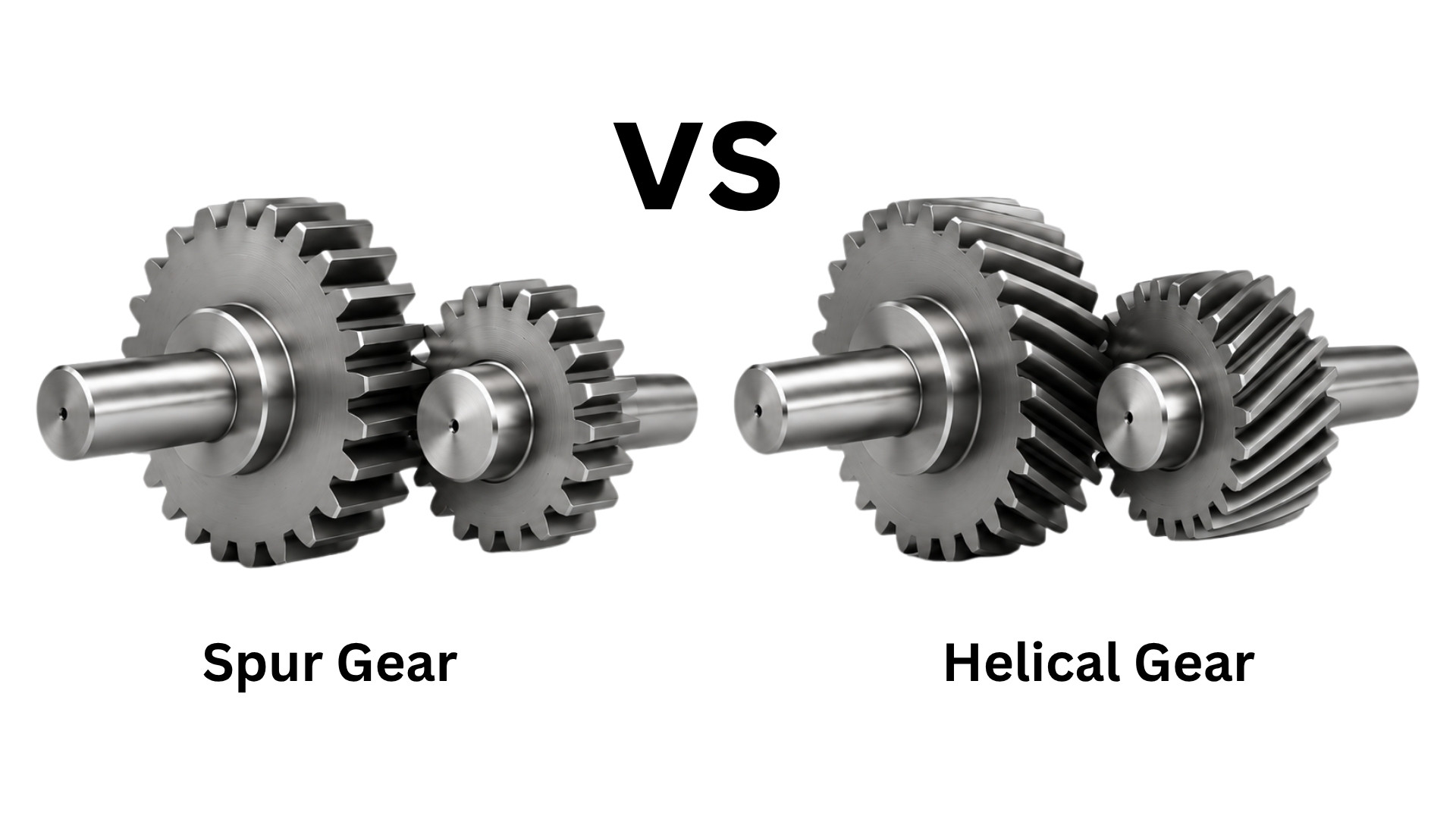
The spur vs helical gear comparison is one of the most common engineering decisions in gear selection. Here is a direct comparison across the key parameters.
| Parameter | Spur Gear | Helical Gear |
| Tooth orientation | Straight, parallel to axis | Angled (helix angle 15–45°) |
| Noise level | Higher (abrupt engagement) | Lower (gradual engagement) |
| Efficiency | 95–99% (slightly higher) | 94–98% (axial friction losses) |
| Load capacity | Moderate | Higher (greater contact ratio) |
| Axial (thrust) load | None | Yes – requires thrust bearings |
| Manufacturing cost | Lower | Higher |
| Shaft orientation | Parallel only | Parallel or crossed |
| Best applications | Low-to-medium speed, high precision | High speed, heavy load, quieter |
Materials Used for Spur Gears
The choice of material directly affects strength, wear resistance, noise, weight, and cost. Common materials include:
| Material | Key Properties | Typical Use |
| Alloy Steel (e.g. 20CrMnTi) | High strength, wear resistant, hardenable | Automotive, heavy machinery |
| Carbon Steel (e.g. C45) | Good strength, cost-effective | General industrial gears |
| Cast Iron | Good vibration damping, cheap | Low-speed, low-load applications |
| Brass / Bronze | Corrosion resistant, low friction | Instruments, marine, food machinery |
| Nylon (PA6/PA66) | Quiet, self-lubricating, lightweight | Appliances, light-duty robotics |
| Acetal (POM) | Stiff, low friction, dimensionally stable | Precision instruments, printers |
Common Failures & Maintenance
Common Failure Modes
- Tooth wear: Gradual material loss on tooth flanks due to sliding contact; accelerated by insufficient lubrication or abrasive contamination.
- Pitting: Surface fatigue causing small craters (pits) on tooth faces; caused by excessive contact stress over many load cycles.
- Tooth breakage: Sudden fracture of one or more teeth due to impact loading, overload, or pre-existing cracks at the tooth root.
Maintenance Best Practices
- Proper lubrication: Use the correct grade of gear oil or grease; maintain oil level and change at manufacturer-specified intervals.
- Alignment: Ensure shaft parallelism and correct centre distance to prevent edge loading and uneven tooth contact.
- Regular inspection: Periodically inspect tooth flanks for wear, pitting, or cracks using visual checks or non-destructive testing.
Conclusion
Spur gears are the foundation of mechanical power transmission. Their straight-tooth, parallel-shaft design delivers exceptional efficiency, low manufacturing cost, and reliable performance across countless applications – from precision instruments and robotics to automotive gearboxes and industrial machinery.
When choosing a spur gear, consider the required gear ratio, load, speed, noise tolerance, and environmental conditions. Pair the right material and quality grade with proper lubrication and alignment to maximise service life.
FAQs:
A spur gear is a cylindrical gear with straight teeth cut parallel to its rotational axis. It meshes with an adjacent spur gear or rack on a parallel shaft to transmit rotational motion and mechanical power. It is the simplest, most efficient, and most widely produced gear type in engineering.
A spur gear works by direct tooth engagement between a driver gear and a driven gear. When the driver rotates, its teeth push against the teeth of the driven gear, transferring force and motion. The gear ratio – determined by the number of teeth on each gear – governs the change in speed and torque between the two shafts.
Spur gears are noisier than helical gears because their straight teeth engage and disengage abruptly across the full tooth width. This sudden impact creates vibration and noise, especially at high speeds. Helical gears reduce noise by gradually engaging teeth along the helix angle, which smooths out the contact force.
Spur gears are used across almost every industry: automotive gearboxes, industrial machinery (lathes, pumps, compressors), conveyors, robotics, packaging equipment, agricultural machinery, clocks and instruments, and household appliances such as washing machines and food processors.
Spur gears have straight teeth parallel to the shaft axis, while helical gears have teeth cut at an angle (helix angle). Helical gears run quieter and can carry heavier loads due to a higher contact ratio, but generate axial thrust and are more expensive to manufacture. Spur gears are simpler, cheaper, and produce no axial load.
Common spur gear materials include alloy steel (for high-strength applications), carbon steel (general purpose), cast iron (low-speed, vibration-damping), brass or bronze (corrosion resistance), and engineering plastics such as nylon or acetal (for quiet, lightweight, or self-lubricating requirements).