
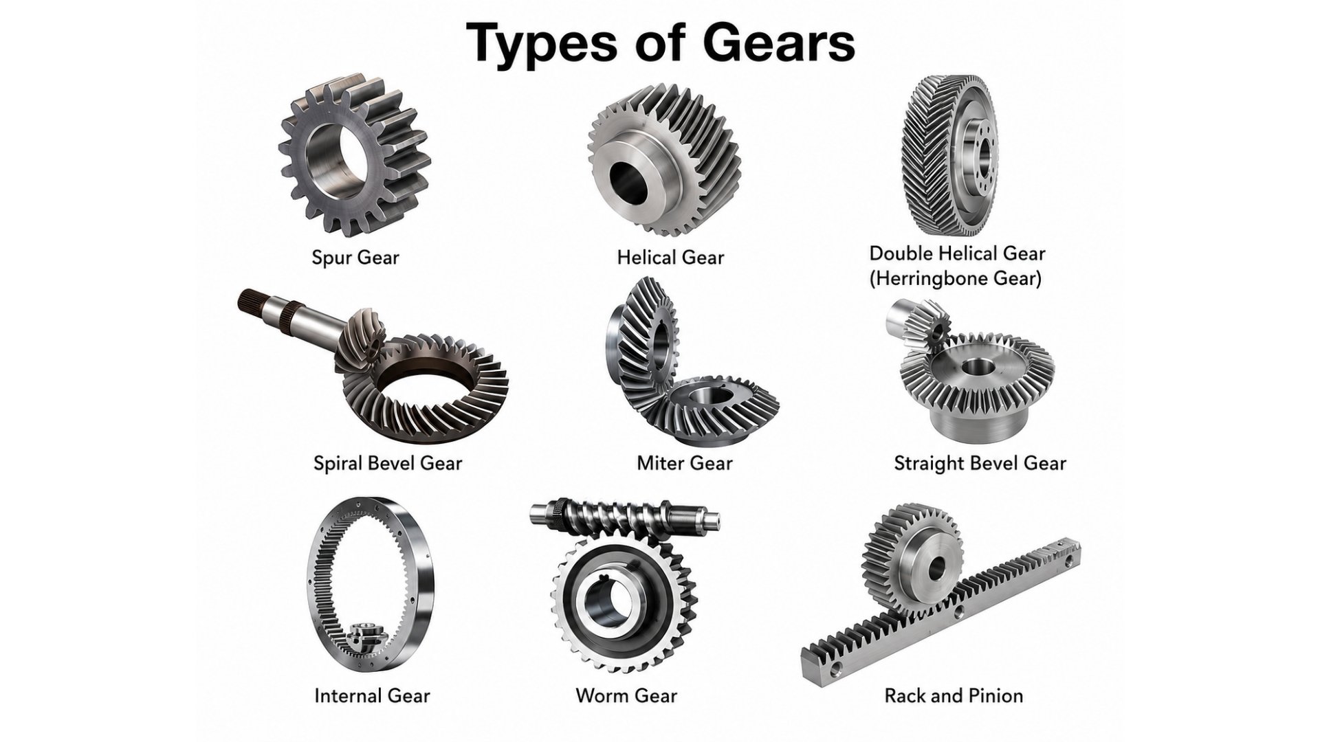
There are 3 main categories of gears – parallel-axis gears (spur, helical, herringbone, rack and pinion, internal), intersecting-axis gears (bevel, spiral bevel, miter), and non-parallel/non-intersecting gears (worm, hypoid, screw). The most widely used types are spur, helical, bevel, worm, and planetary gears. Each type differs in shaft orientation, tooth geometry, noise level, efficiency, and application.
Gears are among the oldest mechanical components in human history – Aristotle described them in 330 BC, and today they power everything from wristwatches to wind turbines. Yet with more than a dozen distinct gear types available, choosing the wrong one leads to noise, heat, premature wear, or outright system failure.
Whether you’re a student trying to understand the basics or an engineer specifying components for a new machine, this guide covers every major gear type – what it is, how it works, its advantages and disadvantages, efficiency range, and real-world applications. By the end, you’ll also have a step-by-step framework for selecting the right gear for any application.
What Is a Gear?
A gear is a rotating mechanical component with precisely cut teeth that mesh with the teeth of another gear to transmit torque, change speed, or alter the direction of motion. Unlike belt drives, gears transmit power through positive engagement – the teeth physically interlock, so there is no slipping and no loss of timing.
When two gears mesh, three things can happen depending on their relative sizes:
- Speed reduction: a small driving gear turning a large driven gear slows rotation and multiplies torque.
- Speed increase: a large driving gear turning a small driven gear increases rotation speed and reduces torque.
- Direction change: intersecting or skew-axis gear pairs redirect the axis of rotation.
Gear ratio is the fundamental number governing this relationship:
Gear ratio = Driven gear teeth ÷ Driving gear teeth
A 20-tooth gear driving a 60-tooth gear produces a 3:1 ratio – the output shaft turns at one-third the input speed, with approximately three times the torque.
Key Gear Terms You Need to Know
| Term | Definition |
| Pinion | The smaller of two meshing gears |
| Module | Standard unit of tooth size in metric systems |
| Diametral pitch | Tooth size unit in imperial systems |
| Pressure angle | Angle of force between meshing teeth (standard: 20°) |
| Backlash | Clearance between mating teeth; affects positional accuracy |
| Gear train | Two or more gears working in series to achieve a target ratio |
| Involute profile | The standard tooth shape – maintains constant velocity ratio |
How Gears Are Classified
The most practical way to classify gears is by the orientation of the shafts they connect. This determines which gear families are geometrically possible for a given installation.
| Category | Shaft Relationship | Primary Examples |
| Parallel-axis | Shafts run side by side | Spur, helical, herringbone, rack & pinion, internal |
| Intersecting-axis | Shafts meet at a point (usually 90°) | Straight bevel, spiral bevel, miter |
| Non-parallel, non-intersecting | Shafts pass each other in skewed space | Worm, hypoid, screw gear |
Start every gear selection decision here. Once you know your shaft geometry, you’ve already eliminated most gear types from consideration.
Parallel-Axis Gear Types
These are the most common gears in mechanical engineering, used wherever shafts are arranged side by side.
1. Spur Gear – The Most Common Gear Type

Spur gears have straight teeth cut parallel to the shaft axis. They are the simplest, cheapest, and most efficient gear type available.
How they work: Teeth engage abruptly along the full face width simultaneously. This produces a characteristic noise at high speeds but delivers excellent efficiency – up to 99% – in lower-speed applications.
Advantages: Very simple to design and manufacture, high efficiency, no axial thrust on bearings, easy to maintain and replace.
Disadvantages: Noisy and prone to vibration at high speeds due to sudden tooth contact. Not suitable for heavy shock loads.
Efficiency: Up to 99% Typical ratio range: 1:1 to 6:1 per stage
Real-world applications: Clocks and watches, washing machine drums, conveyor belt drives, gear pumps, simple gearboxes, and any application where cost and simplicity matter more than noise.
2. Helical Gear – Quieter, Stronger, More Versatile

Helical gears have teeth cut at an angle (the helix angle) to the shaft axis. Instead of engaging all at once, teeth slide into mesh gradually – a key difference that changes everything about performance.
How they work: The angled teeth create a continuous rolling contact across the tooth face. This smooths out the load, dramatically reduces noise, and increases load capacity compared to spur gears.
Advantages: Much quieter and smoother than spur gears, handles higher loads, suitable for high-speed applications.
Disadvantages: The angled teeth create axial thrust – a side force that pushes along the shaft. This requires thrust bearings, adding cost and complexity. Slightly lower peak efficiency than spur in some configurations.
Efficiency: 96–99% Typical ratio range: 1:1 to 10:1 per stage
Real-world applications: Automotive manual transmissions, industrial gearboxes, HVAC compressors, machine tool spindles.
Spur Gear vs. Helical Gear – Key Differences
| Factor | Spur Gear | Helical Gear |
| Tooth orientation | Parallel to shaft | Angled (helix angle) |
| Noise level | Higher | Lower |
| Axial thrust | None | Yes – needs thrust bearing |
| Load capacity | Moderate | Higher |
| Cost | Lower | Higher |
| Best for | Simple drives, cost-sensitive | High-speed, quiet, high-load |
3. Double Helical (Herringbone) Gear – Eliminating Axial Thrust

A herringbone gear consists of two opposite helical sections placed side by side, creating a distinctive “V” or chevron tooth pattern. The opposing helix angles cancel out axial thrust entirely.
Best for: Very high-load applications where both smooth operation and zero axial thrust are required – rolling mills, large marine propulsion systems, and power plant turbine drives. Extremely expensive to manufacture due to precision requirements.
4. Internal (Ring) Gear – Compact and Same-Direction

Internal gears have teeth cut on the inside of a hollow ring. The external pinion meshes inside the ring, and both gears rotate in the same direction – unlike external gear pairs.
This makes internal gears exceptionally compact and space-efficient. They’re the outer ring in every planetary gear set, making them a critical component in automatic transmissions and industrial gearboxes.
5. Rack and Pinion – Rotary Motion to Linear Motion

A gear rack is essentially a spur gear with infinite radius – a flat bar with straight teeth. When a circular pinion rolls along the rack, rotary motion converts to linear motion (and vice versa).
Advantages: Simple, rigid, high positional accuracy, unlimited travel length (just add more rack sections).
Limitations: No self-locking; requires a brake if the load must hold position.
Real-world applications: Automotive steering systems, CNC machine tool axis positioning, elevator drive systems, adjustable furniture mechanisms, and camera focusing rails.
Intersecting-Axis Gear Types
When shafts meet at a point – almost always at 90° – the bevel gear family takes over.
1. Straight Bevel Gear – Standard 90° Direction Change

Straight bevel gears have a conical shape with straight teeth tapering toward the apex. They’re the simplest way to transmit power around a corner.
Best for: Low-to-moderate speed applications where direction change is needed and cost matters. Common in hand drills, agricultural equipment, and basic differentials.
Limitation: Noisy and rough at high speeds due to abrupt tooth engagement – the same problem spur gears have.
Efficiency: 97–99%
2. Spiral Bevel Gear – The High-Performance Bevel

Spiral bevel gears have curved, oblique teeth. Like helical gears vs. spur gears, the curved teeth engage progressively, dramatically reducing noise and vibration while increasing load capacity.
Why they’re used in performance applications: Quieter, stronger, and more efficient than straight bevel gears. The curved contact also distributes load more evenly, extending gear life significantly.
Trade-offs: More complex to manufacture, higher cost, generates axial thrust.
Real-world applications: Automotive rear-axle differentials, aerospace gearboxes, helicopter tail rotor transmissions, and high-quality machine tools.
3. Miter Gear – Direction Change Only, No Ratio Change

Miter gears are a special case of bevel gears where both gears have equal tooth counts. The ratio is always 1:1. They change direction – that’s all.
Use miter gears when you need to redirect shaft rotation by 90° without any speed or torque change. Common in right-angle drives for hand tools, packaging machinery, and instrument panels.
Non-Parallel, Non-Intersecting Gear Types
These gear types handle the most challenging geometry: shafts that neither run parallel nor meet at a point.
1. Worm Gear – High Ratio, Self-Locking

A worm gear set consists of a threaded worm (resembling a screw) that drives a worm wheel. The shafts are at 90° but don’t intersect – they pass each other in offset planes.
The defining characteristic: A single worm-and-wheel stage can achieve gear ratios from 5:1 to over 100:1 – something no other single-stage gear type can match.
Self-locking: At low lead angles, the worm can drive the wheel but the wheel cannot back-drive the worm. This passive holding capability is used intentionally in elevators, hoists, and gate mechanisms as a safety feature.
The efficiency trade-off: Worm gears use sliding tooth contact rather than rolling contact. This generates significant friction, heat, and power loss – efficiency typically ranges from 50–90%, far below other gear types. High-duty-cycle applications require careful thermal management.
Efficiency: 50–90% (lead angle dependent) Typical ratio range: 5:1 to 100:1+
Real-world applications: Elevator lifts, conveyor backstops, guitar machine heads, automotive steering columns (older designs), stand mixers, boat trailer winches.
Worm Gear vs. Planetary Gear – Which to Choose?
| Factor | Worm Gear | Planetary Gear |
| Ratio (single stage) | 5:1 to 100:1+ | 3:1 to 10:1 |
| Efficiency | 50–90% | 90–97% |
| Self-locking | Yes (low lead angle) | No |
| Heat generation | Higher | Lower |
| Best for | High ratio, holding loads, low duty cycle | Compact high torque, continuous operation |
Rule of thumb: Choose worm when you need a very high ratio in one stage or passive holding behavior, and the duty cycle is manageable. Choose planetary when you need compact high torque with better efficiency for continuous operation.
2. Hypoid Gear – The Automotive Differential Standard
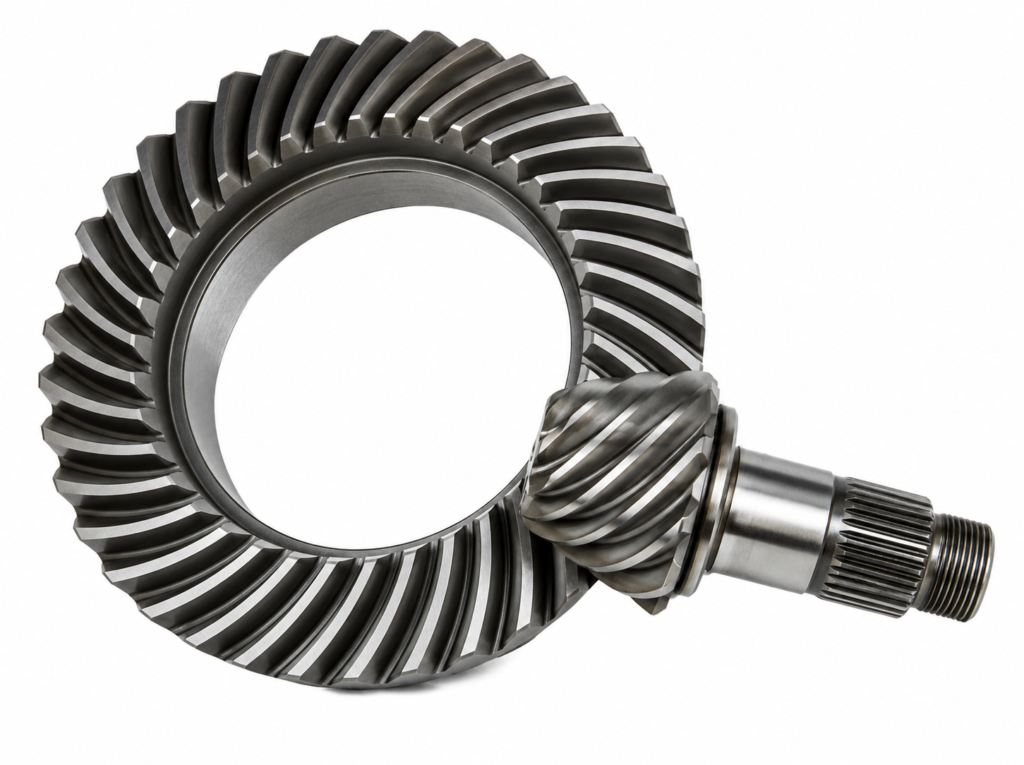
Hypoid gears look like spiral bevel gears but with an important difference: the pinion axis is offset from the ring gear axis. The shafts don’t intersect.
This offset allows the pinion shaft to pass below the ring gear centerline – which in a rear-wheel-drive vehicle means the driveshaft can run lower, lowering the floor, reducing the center of gravity, and improving cabin space. This is why hypoid gears are the standard choice in virtually all automotive rear-axle differentials.
Important maintenance note: Hypoid gears require special hypoid-specific extreme pressure (EP) lubricant. Standard gear oil will fail under the sliding contact loads hypoid geometry produces.
Efficiency: 90–95%
Special and Advanced Gear Types
1. Planetary (Epicyclic) Gear – Maximum Torque in Minimum Space
A planetary gear set is a system, not a single gear type. It consists of three elements:
- Sun gear – center input/output
- Planet gears – multiple gears orbiting the sun
- Ring gear – outer internal gear that surrounds the planets
- Planet carrier – the frame holding the planet gears
Why planetary gears are exceptional: Load is shared simultaneously across multiple planet gears. Three planet gears means three contact points sharing the load – this is why planetary systems deliver very high torque density in an extremely compact envelope, often outperforming a worm gear at the same ratio while running far more efficiently.
Configuration flexibility: Depending on which element is held fixed, driven, or used as output, the same planetary set produces different ratios. This is the foundation of multi-speed automatic transmissions.
Efficiency: 90–97% Typical ratio range: 3:1 to 10:1 per stage (up to 100:1+ in multi-stage planetary)
Real-world applications: Every automatic car transmission, electric vehicle single-speed reduction drives, wind turbine gearboxes, industrial servo gearheads, power tools, and robotics.
2. Harmonic Drive (Strain Wave Gear) – Zero Backlash Precision
Harmonic drives are unlike any other gear type. They use elastic deformation of a thin flexible metal spline to achieve meshing – there are no conventional rigid tooth pairs engaging and disengaging.
Three components:
- Wave generator (elliptical cam + bearing – the input)
- Flex spline (thin-walled flexible cylinder with external teeth – the output)
- Circular spline (rigid ring with internal teeth – fixed housing)
The wave generator deforms the flex spline into an ellipse, creating tooth engagement at two points 180° apart. As the wave generator rotates, the engagement points travel around, and the flex spline “crawls” relative to the circular spline – achieving enormous reduction ratios in a tiny, lightweight package.
Why engineers specify harmonic drives: Near-zero backlash. In robotic joints, zero backlash means the arm returns to exactly the same position repeatedly. This is non-negotiable in surgical robots, semiconductor manufacturing, satellite antenna pointing, and any precision automation application.
Efficiency: 80–90% Typical ratio range: 30:1 to 300:1 in a single stage
Real-world applications: Industrial and collaborative robot joints, surgical robotic arms, spacecraft articulation mechanisms, satellite antenna drives, CNC rotary tables.
3. Cycloidal Drive – Shock-Resistant High Torque
Cycloidal drives use an eccentric shaft to spin a cycloidal disc against stationary ring pins, with output pins picking up motion from the disc. The result is very high contact ratio – many pins engaged simultaneously – making cycloidal drives extremely resistant to shock loads.
Used increasingly in collaborative robots (cobots) and heavy industrial robotic arms where shock resistance and backdrivability are both required.
Master Gear Comparison Table
| Gear Type | Shaft Orientation | Efficiency | Ratio Range | Noise | Self-Locking | Complexity | Relative Cost |
| Spur | Parallel | Up to 99% | 1:1 to 6:1 | High | No | Low | Low |
| Helical | Parallel | 96–99% | 1:1 to 10:1 | Low | No | Medium | Medium |
| Herringbone | Parallel | 96–99% | 1:1 to 10:1 | Very low | No | Very high | Very high |
| Internal (Ring) | Parallel | 97–99% | 3:1 to 10:1 | Low | No | Medium | Medium |
| Rack & Pinion | Parallel/Linear | 95–99% | N/A | Medium | No | Low | Low–Med |
| Straight Bevel | Intersecting | 97–99% | 1:1 to 4:1 | High | No | Medium | Medium |
| Spiral Bevel | Intersecting | 97–99% | 1:1 to 6:1 | Low | No | High | High |
| Miter | Intersecting | 97–99% | 1:1 only | Medium | No | Medium | Medium |
| Worm | Skew 90° | 50–90% | 5:1 to 100:1 | Low | Yes | Medium | Medium |
| Hypoid | Skew offset | 90–95% | 3:1 to 10:1 | Low | No | High | High |
| Planetary | Parallel | 90–97% | 3:1 to 100:1+ | Low | No | High | High |
| Harmonic Drive | Compact | 80–90% | 30:1 to 300:1 | Very low | Yes | Very high | Very high |
| Cycloidal | Eccentric | 90–95% | 6:1 to 119:1 | Medium | No | Very high | Very high |
For a better understanding of the types of gears, watch this video carefully.
How to Choose the Right Gear Type
Follow these six steps in order. Each step narrows your options significantly.
Step 1 – Shaft orientation first.
Are your shafts parallel, intersecting, or skew? This is the most important question. Parallel shafts → spur/helical family. Intersecting shafts → bevel family. Skew (non-parallel, non-intersecting) → worm/hypoid family. Never choose a gear type before answering this.
Step 2 – Define your required ratio.
Low ratio (1:1 to 5:1): spur, helical, bevel are all candidates. Medium ratio (5:1 to 20:1): worm or planetary. High ratio (20:1 to 300:1+): worm, harmonic drive, or multi-stage planetary.
Step 3 – Assess speed and load.
High speed with smooth operation required → helical or spiral bevel. Very high torque in compact space → planetary. Continuous high-torque duty → avoid worm (overheating risk); use planetary.
Step 4 – Noise and vibration requirements.
Noise-sensitive environment (medical, office, residential) → helical, herringbone, spiral bevel, or planetary. Noise is acceptable → spur or straight bevel are simpler and cheaper.
Step 5 – Self-locking required?
If the load must hold position without an active brake (elevators, hoists, gates) → worm gear at low lead angle, or harmonic drive. If backdrivability is required → avoid worm; choose planetary or helical.
Step 6 – Space, weight, and budget.
Most compact solution → planetary or harmonic drive. Lowest cost → spur gear. Lightweight + compact + zero backlash → harmonic drive. Balance these constraints against steps 1–5 to reach your final selection.
Gear Types by Industry
Automotive:
Helical gears in manual transmissions; planetary gears in automatic transmissions; hypoid gears in rear-axle differentials; rack and pinion in steering; spiral bevel in 4WD transfer cases.
Robotics and automation:
Harmonic drives in robot joints (zero backlash); cycloidal drives in cobot joints (shock resistance); planetary gears in servo gearheads and linear actuators.
Aerospace and defense:
Spiral bevel gears in helicopter tail rotor transmissions; planetary gears in aircraft engine accessory drives; harmonic drives in satellite antenna pointing mechanisms.
Industrial machinery:
Helical gears in heavy-duty gearboxes and conveyor drives; worm gears in elevator drives and conveyor backstops; herringbone gears in rolling mills.
Consumer products:
Spur gears in clocks, toys, and can openers; worm gears in guitar machine heads, window blinds, and stand mixers; rack and pinion in adjustable furniture.
Common Gear Selection Mistakes
Mistake 1 – Using a worm gear for continuous heavy-duty operation.
Worm gears generate significant heat from sliding contact. Running them at high duty cycles without adequate thermal management leads to lubricant breakdown and premature failure. Fix: switch to planetary if continuous high torque and efficiency are both required.
Mistake 2 – Using spur gears in a noise-sensitive, high-speed application.
Abrupt tooth engagement creates noise and vibration that increases with speed. Fix: switch to helical gears for quieter, smoother operation at speed.
Mistake 3 – Ignoring axial thrust from helical gears.
Helical teeth generate axial thrust that loads the shaft bearings. Ignoring this leads to bearing failure and misalignment. Fix: specify thrust bearings, or switch to herringbone gears to cancel the thrust internally.
Mistake 4 – Treating worm gear self-locking as a safety brake.
Worm gears are not reliably self-locking under all conditions – vibration, wear, and high lead angles can all allow back-driving. Fix: always add a dedicated mechanical or electromagnetic brake in safety-critical applications.
Mistake 5 – Using plastic gears in high-temperature or high-load environments.
Nylon and acetal gears have low thermal tolerance and limited load capacity. They fail quickly when overloaded or overheated. Fix: switch to metal gears, or address noise/cost concerns through design rather than material.
Mistake 6 – Selecting gear type before defining shaft layout.
No gear type can compensate for incompatible shaft geometry. Fix: always define shaft positions, spacing, and orientation before beginning gear type selection.
FAQs
The four most commonly referenced types are spur gears (simplest, most common), helical gears (quieter, higher load capacity), bevel gears (for direction change on intersecting shafts), and worm gears (for high reduction ratios). Planetary gears are frequently cited as a fifth fundamental type due to their widespread industrial use in transmissions and robotics.
Spur gears are the most common gear type worldwide. Their simple straight-tooth design makes them the easiest and cheapest to manufacture, and their efficiency of up to 99% makes them the default choice for any low-to-moderate speed parallel-shaft drive where noise is not a concern.
Spur gears have straight teeth parallel to the shaft – simple, efficient, and inexpensive, but noisy at high speeds. Helical gears have angled teeth that engage progressively, running quieter and handling higher loads. The trade-off is that helical gears generate axial thrust requiring thrust bearings, and they cost more to manufacture.
Multiple gear types are used in a single vehicle: helical gears in manual transmissions, planetary gears in automatic transmissions, hypoid gears in rear-wheel-drive differentials, rack and pinion in the steering system, and spiral bevel gears in 4WD transfer cases.
Spur gears achieve the highest peak efficiency (up to 99%) for parallel-shaft drives. Helical, internal, and bevel gears follow at 96–99%. Planetary gear systems reach 90–97%. Worm gears are the least efficient common type at 50–90%, depending on lead angle, lubrication, and load.
Planetary gears are used wherever high torque is needed in a compact space. Common applications include automatic transmissions, electric vehicle drive units, wind turbine gearboxes, industrial servo gearheads, and robotics – any application combining compact size, high efficiency, and high torque density.
It depends on the lead angle. Worm gears with small lead angles (under approximately 5°) are effectively self-locking. Worm gears with larger lead angles can be back-driven. In safety-critical applications – elevators, lifts, hoists – never rely on self-locking alone; always add a dedicated brake.
A harmonic drive achieves 30:1 to 300:1 ratios in an ultra-compact, lightweight package with near-zero backlash by using the elastic deformation of a thin flexible metal spline rather than rigid tooth pairs. The zero-backlash property makes harmonic drives the standard choice in robotic joints, surgical instruments, and spacecraft mechanisms where repeatable positional accuracy is critical.
Key Takeaways
1. Start with shaft orientation, not gear type. Parallel shafts → spur/helical/planetary. Intersecting shafts → bevel family. Skew shafts → worm/hypoid. This single question eliminates most options immediately.
2. Spur gears are the default for simple drives. Lowest cost, highest efficiency (up to 99%), easiest to maintain. Switch to another type only when noise, load, ratio, or geometry requirements demand it.
3. Helical gears are the upgrade from spur when noise or load matters. Quieter, stronger, versatile – at the cost of axial thrust and higher price. The most common gear type in industrial gearboxes.
4. Worm gears are unmatched for high single-stage ratio and self-locking. But their 50–90% efficiency, heat generation, and duty-cycle limitations mean they’re not appropriate for continuous high-load operation. Use planetary instead when duty cycle or efficiency matters.
5. Planetary gears deliver the best combination of compactness, efficiency, and torque density. They are the preferred choice for automotive transmissions, robotics, and any application where high torque must fit in a small space and run continuously.
6. For precision robotics and zero-backlash applications, harmonic drives have no equal. They are the only gear type combining ultra-high single-stage reduction, near-zero backlash, and compact lightweight form factor.
7. Never select a gear type before considering the full system. Shaft geometry, required ratio, speed, load, noise, duty cycle, space, and budget all constrain the solution. A gear that’s perfect in isolation but wrong for the installation will fail.