
Why spreading resistance, wick design, vapor-space thickness, and system integration determine real-world performance
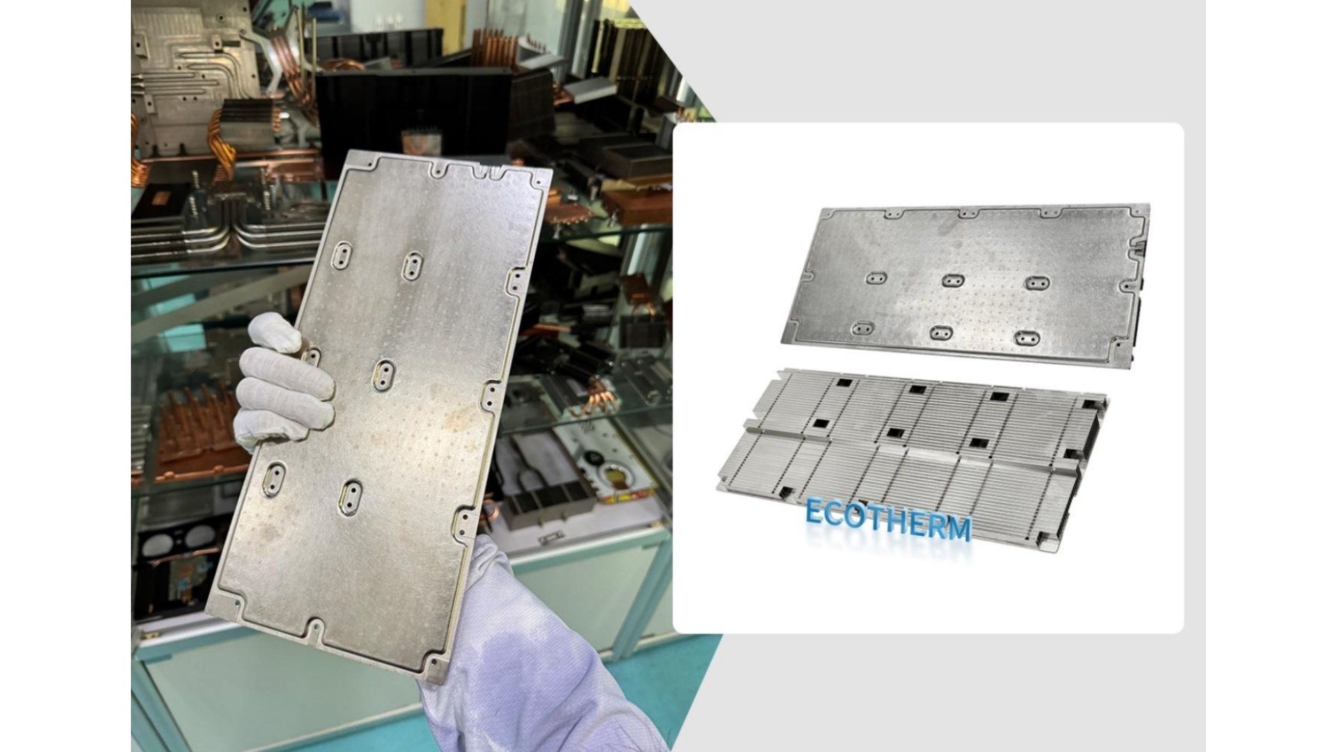
Higher electronic performance increasingly means more heat concentrated into a smaller footprint. A conventional heat sink may still have enough fin area and airflow to reject the total heat load, yet the component can remain too hot because the metal base cannot spread that heat across the available fin field. In this situation, the limiting factor is spreading resistance rather than the number of fins.
That distinction changes the design question. Instead of asking only how large the heat sink should be, engineers must ask how efficiently heat can move from a compact source into the entire cooling surface. A vapor chamber is one option for solving that problem, but its performance depends on far more than simply replacing a copper plate with a sealed chamber.
Heat Spreading and Heat Rejection Are Different Jobs
Every air-cooled electronic system contains a thermal path: heat passes from the semiconductor package through a thermal interface, into the heat sink base, through the fins, and finally into the air. Each stage adds thermal resistance.
If airflow is the main bottleneck, a better fan or a lower-restriction fin stack may reduce temperature. If the thermal interface is poor, improving the base cannot eliminate the contact problem. But when the center of the base is hot and the outer fins remain much cooler, the heat sink is probably not using its full surface area. That temperature pattern is a classic sign of spreading resistance.
Copper and aluminum conduct heat well, but a solid plate still develops a temperature gradient when a small source feeds a much larger base. Making the plate thicker can improve lateral conduction, although it also adds mass, material, and height. Beyond a certain point, more metal produces diminishing thermal benefit.
How a Vapor Chamber Moves Heat
A Vapor chamber is a vacuum-sealed, usually flat enclosure containing a small amount of working fluid, an internal wick, and mechanical supports. One portion operates as the evaporator above the heat source, while cooler portions act as condensers.
When heat enters the evaporator region, the working fluid absorbs energy and changes from liquid to vapor. The vapor moves through the low-pressure internal space toward cooler regions. There it condenses, releases latent heat to the chamber wall, and becomes liquid again. A porous wick returns the liquid to the heat input region by capillary action.
The repeated evaporation, vapor transport, condensation, and liquid-return cycle spreads energy across the chamber in two dimensions. The chamber does not destroy heat and does not replace the fins or airflow. Its job is to deliver heat to more of the available heat-rejection surface so that the external heat sink can work more uniformly.
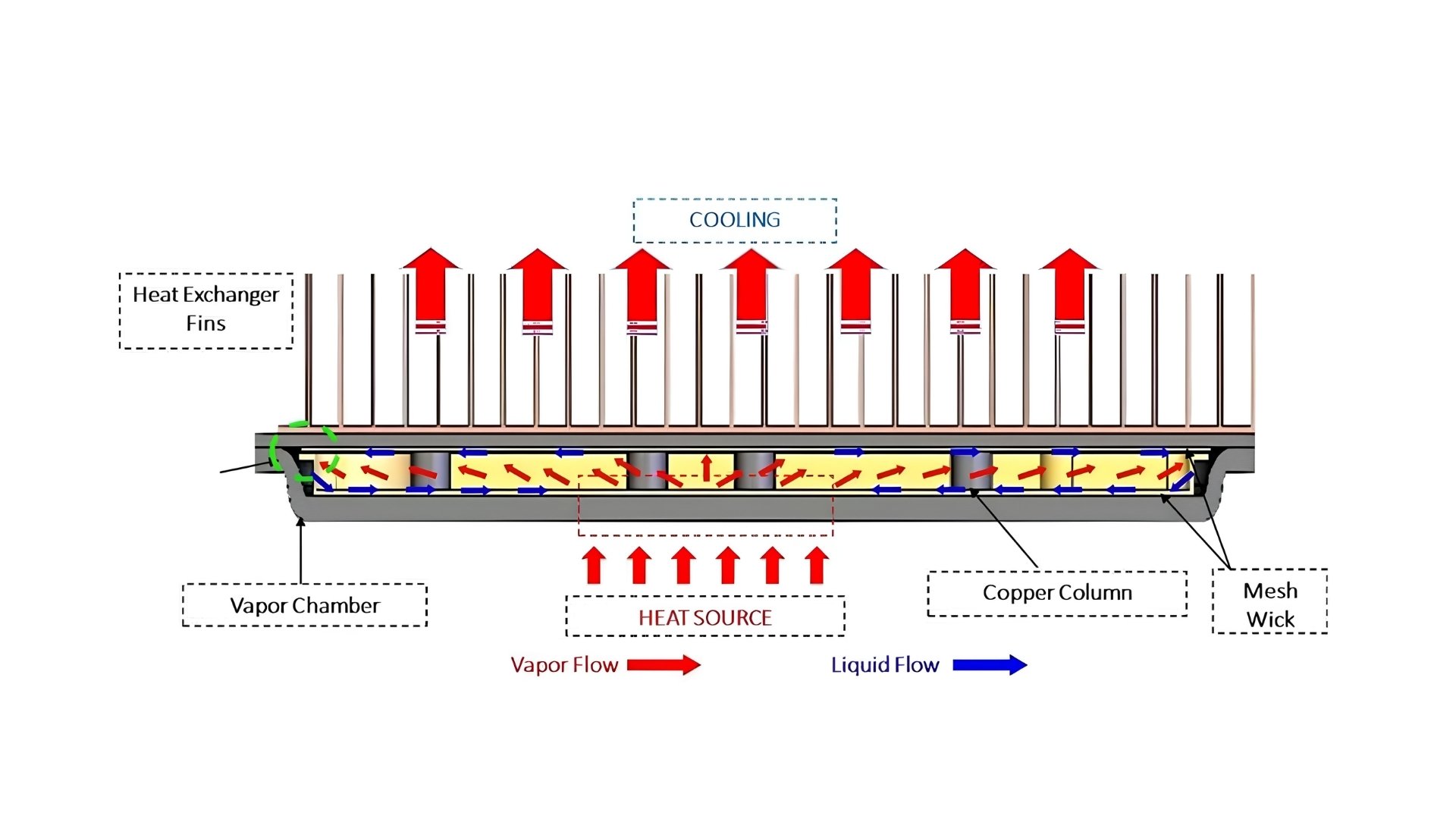
Figure 1. Phase-change circulation inside a finned vapor chamber heat sink: vapor carries energy outward, while liquid returns through the wick.
The Internal Features That Control Performance
Although the operating principle is simple to describe, a useful design must balance vapor flow, liquid return, structural support, materials, and manufacturing tolerances. Four vapor chambers with the same external dimensions can behave very differently if these internal details change.
Wick Structure: Capillary Pressure Versus Permeability
The wick provides the capillary pressure that pumps condensate back toward the evaporator. Common approaches include sintered metal powder, woven mesh, grooves, metal foam, and hybrid structures. Fine pores can generate strong capillary pressure, while larger and more open pathways generally reduce liquid-flow resistance. Improving one property can weaken the other, so the best structure is not simply the smallest pore size.
Hybrid or graded wicks attempt to separate these functions. A fine-pore region can support liquid supply close to the evaporator, while a more permeable region provides a lower-resistance return path. The selection also depends on orientation, source location, expected acceleration, and the possibility of local dry-out.
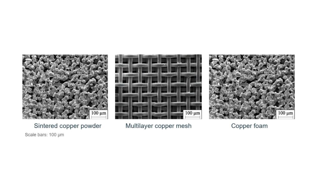
Figure 2. Examples of wick microstructures. Pore scale, permeability, and capillary pressure must be balanced for the intended load and orientation.
Vapor Space and Chamber Thickness
A thinner chamber fits more easily into compact products, but reducing the internal height narrows both the vapor path and the liquid-return structure. Vapor pressure drop can rise, the wick can hold less liquid, and the internal support pattern may occupy a greater share of the available flow area.
This is why ultra-thin design is an optimization problem rather than a race toward the smallest possible number. The required thickness depends on heat load, source area, spreading distance, working fluid, wick geometry, orientation, allowable deformation, and manufacturing capability.
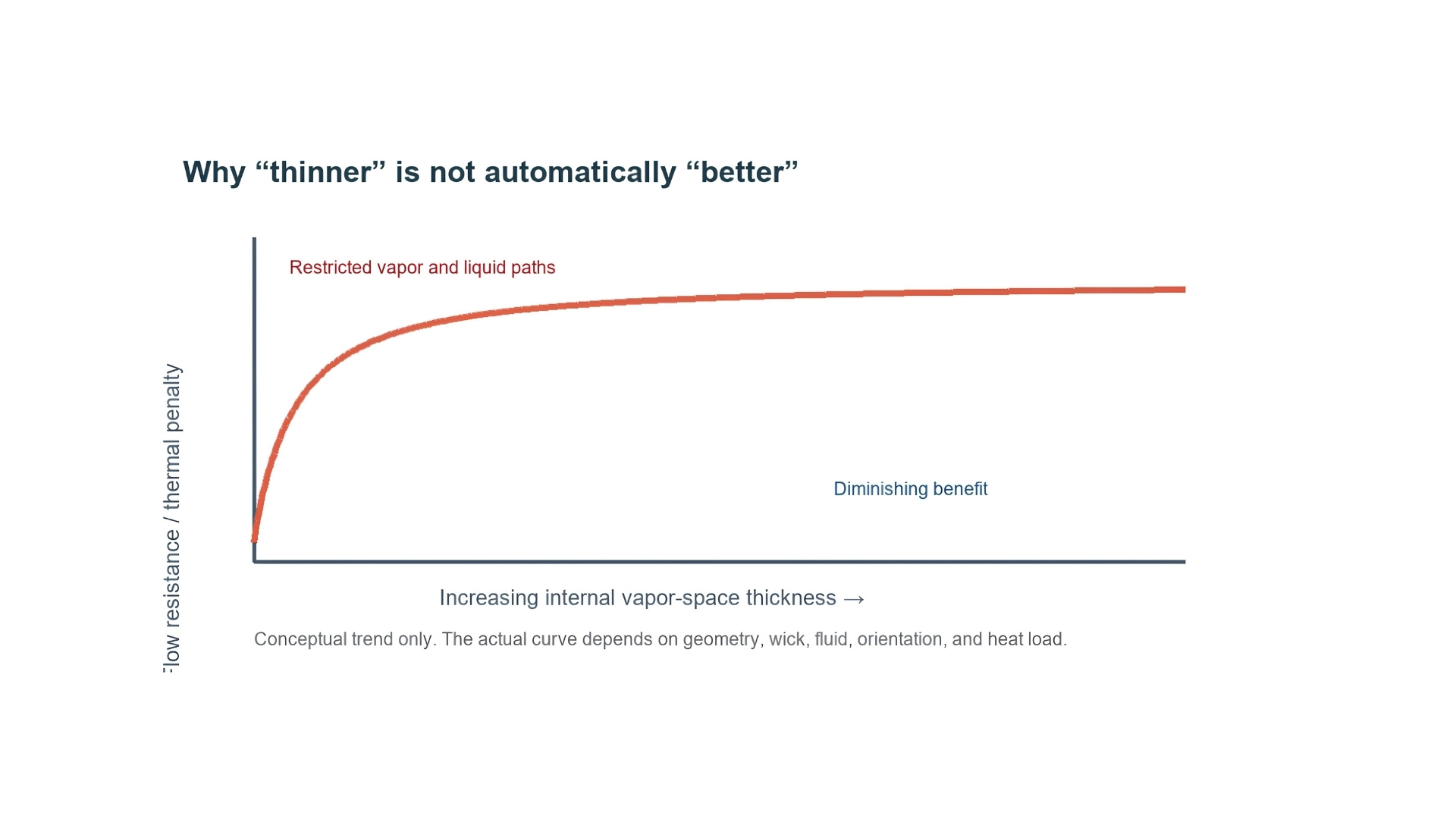
Figure 3. A qualitative design trend: making the internal vapor space extremely thin can increase flow resistance and thermal penalty. This is a conceptual diagram, not universal performance data.
Working Fluid and Fill Ratio
The working fluid must be compatible with the shell and wick and must operate effectively across the intended temperature range. Water is widely used with copper for electronics operating near ordinary equipment temperatures, but other environments can require different fluid-material pairs.
The fluid charge also matters. Too little fluid can leave the evaporator starved during high load, while too much can reduce vapor volume or flood regions needed for evaporation. The appropriate charge is design-specific and must be established through controlled manufacturing and testing.
Support Columns, Flatness, and Sealing
Atmospheric pressure acts on the evacuated shell, and internal pressure changes as temperature rises. Support columns or other internal structures prevent the broad faces from collapsing or bulging. Their geometry and spacing affect mechanical strength, vapor movement, liquid return, mass, and local thermal paths.
External flatness is equally important. A high-performance chamber can be undermined by poor contact with the semiconductor package or fin base. Shell forming, wick attachment, evacuation, fluid charging, sealing, and final joining to the heat sink therefore need to be treated as part of one manufacturing system.
Vapor Chamber, Heat Pipe, or Solid Base?
Solid Metal Base
A solid aluminum or copper base is usually the simplest and most economical option when heat flux is moderate, the source is not extremely small, and base temperature uniformity is acceptable. It has no internal fluid system and can be manufactured using familiar extrusion, machining, forging, or skiving processes.
Heat Pipes
A heat pipe is particularly effective when heat must travel along a defined path from a source to a remote fin stack. Several pipes can be embedded in a base to increase coverage, but the result still consists of discrete transport paths. Pipe routing, bending radius, contact area, and attachment quality affect the final performance.
Vapor Chambers
A vapor chamber is most attractive when a compact source must feed a much larger fin field, when several nearby components share one base, or when a low-profile assembly requires strong planar spreading. It may also simplify the thermal interface between a broad fin stack and a concentrated device.
No option is automatically superior. A vapor chamber adds manufacturing complexity and cost. If the real bottleneck is inadequate airflow, a poor interface, or an undersized fin stack, changing the base alone may deliver little improvement.
Applications Driven by Concentrated Heat
The same design logic appears across several industries. CPUs, GPUs, and AI accelerators produce large heat loads within compact packages. Power modules in inverters, motor drives, and charging equipment may place several concentrated sources on a shared base. Laser and optical systems need temperature uniformity to maintain stable output. Telecommunications equipment combines continuous operation with restricted space and challenging ambient conditions.
In each case, the important variables are not just total watts. Source dimensions, peak heat flux, source spacing, permissible case or junction temperature, airflow, orientation, duty cycle, vibration, and service environment all influence the correct solution.
A Practical Evaluation Process
A reliable selection process starts by mapping every heat source, including its dimensions, power range, location, and allowable temperature. Engineers can then estimate the thermal-resistance budget and determine whether the dominant limitation is the interface, base spreading, fin convection, or external airflow.
Alternative concepts should be compared at system level: a solid base, a heat-pipe assembly, a vapor chamber, and—when the heat load requires it—a liquid-cooled cold plate. Thermal simulation can reveal temperature gradients and underused fin regions, but the model should include realistic contact resistance and boundary conditions.
Prototypes should be tested at maximum expected load, worst-case ambient temperature, and every relevant orientation. Measuring only the center temperature is not enough; temperatures across the base and fin field show whether heat is being distributed effectively. Transient loads, thermal cycling, vibration, leakage integrity, and dimensional stability may also be important for the intended product.
Conclusion
Vapor chambers are best understood as heat spreaders within a complete thermal system. Their two-phase cycle can move concentrated heat across a broad plane, but final performance still depends on the interface, wick, vapor space, fluid charge, support structure, fins, airflow, and manufacturing quality.
The technology becomes valuable when spreading resistance is a measured or well-supported bottleneck. When engineers define that bottleneck clearly and validate the design under realistic conditions, a vapor chamber can help a cooling system use its available area more effectively without relying on an excessively thick solid-metal base.